The first requirement for the implementation of an architectural project is to understand the architectural drawings, also called tables or plans. If you want to know how to read these drawings and understand exactly what they mean, just follow the next steps.
Steps
Part 1 of 4: Background information

Step 1. Read the title page
The title page indicates the name and location of the work, the name, address and contact details of the designer and the date of the project. It is very similar to a book cover and may contain an illustrative image of the finished work that shows what the built building will look like in its context.
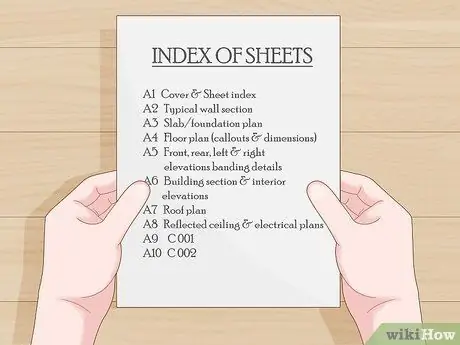
Step 2. Read the table of contents
The index lists the tables specifying the title, the identification code and occasionally the drawing scale and the project notes.
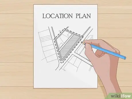
Step 3. Read the general floor plan
This table shows a map of the area where the building will be built, and an enlarged map of the construction site, in order to give enough information to locate the building in relation to nearby urban areas and roads. This table is not present in all projects.
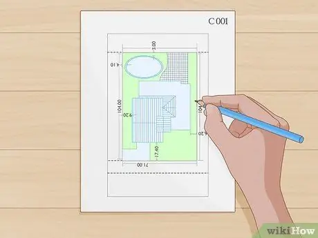
Step 4. Read the construction site plans
These tables are usually numbered with the prefix " C.", for example Table" C 001 "," C 002 ", and so on. These floor plans include several tables that provide the following information:
- Topographic information. These allow the builder to know the topographical characteristics of the site, i.e. slope or flatness of the land.
- Demolition plan. This board (or boards) indicates the structural and non-structural portions present on the site that must be demolished before proceeding with construction. Parts that must not be demolished, such as trees, are indicated in the notes.
- Plan of public utility networks. These tables indicate the location of the technological networks existing underground, so that they are safeguarded during excavation and construction works.
Part 2 of 4: Read the architectural drawings
Step 1. A drawing should never be enlarged
If you can't find anything on the drawing at the current scale, ask the architect for larger scale drawings.
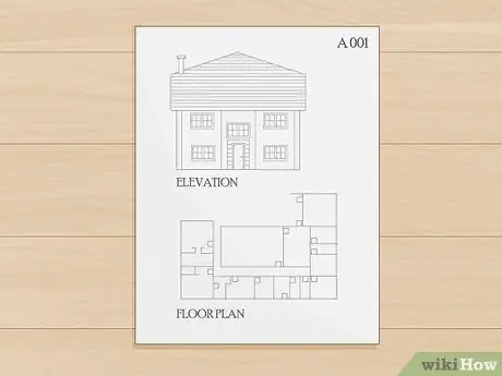
Step 2. Understanding the architectural tables
These tables are generally numbered with the prefix " TO", as in" A 001", or " A1-X", " A2-X", " A3-X", and so on. These tables describe and provide measurements of floor plans, elevations, general and detail sections, and other oriented views of the building. These tables are divided into several sections that together make up the official document that you will need to understand. The parts you need to know are described below.
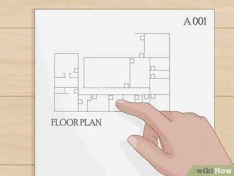
Step 3. Read the floor plans
These tables show the layout of the walls of the building and show elements such as doors, windows, toilets, etc. The distances between (or from) the walls, the measurements of the openings of windows and doors, and the height differences of the floors are highlighted, if they are not at the same height.
- Floor plans can have different levels of detail depending on the progress of the design. In the preliminary project the drawings show only the main characteristics of the spaces.
- In the bidding phase for the works, the drawings will be more detailed, illustrating all the characteristics of the spaces on a larger scale to allow the contractor to make a calculation of the costs.
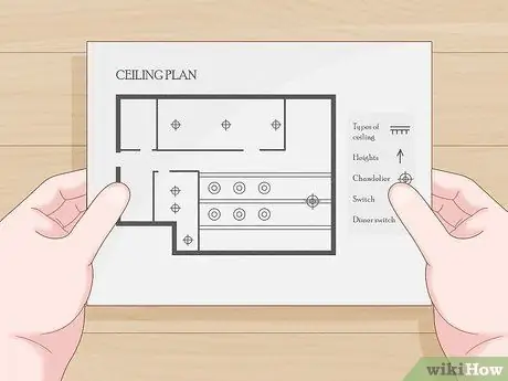
Step 4. Review the ceiling plans
In these plates the architect illustrates the type, height and other characteristics of the ceilings in different parts of the building. Ceiling floor plans may not be present in residential building projects.
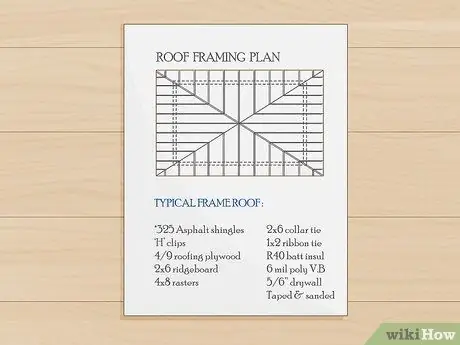
Step 5. Read the roof frame plans
These drawings depict the arrangement of joists, beams, trusses, trusses or other elements of the roof structure, as well as the roof covering and other details of the roof.
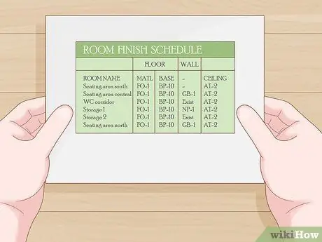
Step 6. Read the finish schedule
This report is generally a table that lists the various finishes of the different environments. It should report the paint colors of each wall, the type and color of the flooring, the height, type and color of the ceiling, the baseboard and other notes and details to achieve the finishes of the affected areas.
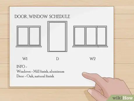
Step 7. Read the window program
This table includes the list of doors describing their type and direction of opening, and information on the windows (often with a typological reference in the plans, for example window or door type "A", "B", etc.). It may also include details on installing (cutting) the flashings, fixing methods and tools. The program can also be separated for door and window finishes (although not in all projects). An example for a window would be "Factory finish, aluminum", for a door "Oak, natural finish".
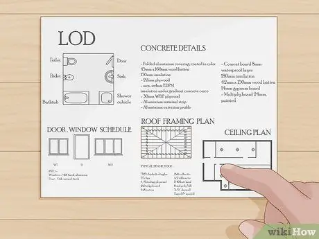
Step 8. Read the remaining details
These may include the arrangement of bathroom fixtures, fixed furnishings, cabinet accessories and other items not specified in other tables. Such as, but not limited to: construction details in concrete, details on doors and windows, on roofing and flashings, on walls, details on doors, wall coverings and more. Each project is different and can specify things that other projects don't, and vice versa. The level of detail is established by the architect for each project. The current trend is to include more and more details, rather than the other way around, so that contractors can have fewer uncertainties and more easily understand what to include and count in the price. Some builders may or may not raise notes about the level of detail, but this has no bearing on what the designer deems appropriate to represent the work.
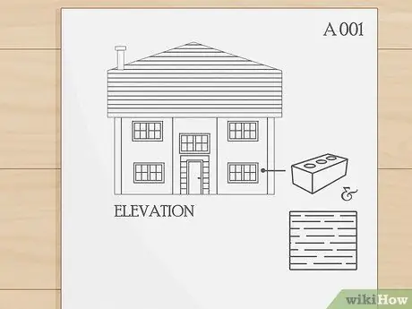
Step 9. Review the reports
These are views from the outside indicating the materials used for the external walls or their cladding (brick, plaster, PVC), the position of the windows and doors from a side view, the pitches of the roof and other elements visible from the outside.
Part 3 of 4: Read the remaining plates
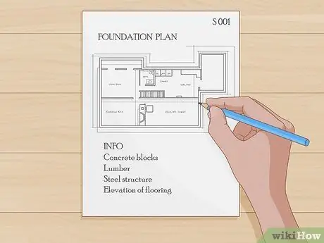
Step 1. Consult the structural tables
The structural tables are numbered with a " S.", as in" S 001". These tables show the reinforcement, foundations, slab thicknesses and other structural components (timber, concrete pillars, structural steel, concrete blocks, etc.). Here are the different aspects of the structural design that you will need to examine:
-
The project of the foundations. These tables describe the size, thickness and elevation of the foundation elements (plinths, back beams), providing specifications for the placement of the reinforcing bars (rebars). The positions of anchor bolts and steel anchor plates embedded in the concrete, and other elements are shown.
The design of a foundation often appears in the first structural table, in addition to the notes regarding the reinforcement, the strength requirements of the concrete and other prescriptions for structural strengths and experimental tests
- The design of the structure. This table indicates the material to be used for the building structure, which could be framed panels of wood or metal, concrete block masonry or steel.
- Intermediate structural projects. These are for multi-storey buildings, where each storey may require support pillars, beams, rafters, planking and other elements.
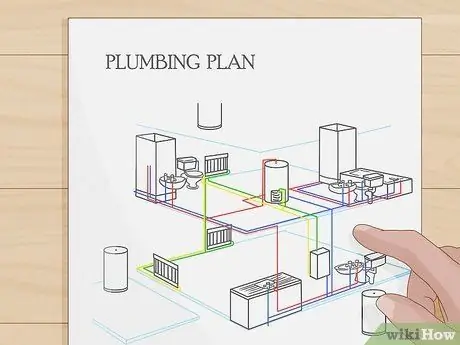
Step 2. Review the plumbing design
The drawings of the plumbing system are numbered with the prefix " P.". These tables show the location and type of piping enclosed in the building. Keep in mind that small residential building projects often do not contain the plumbing diagram. Here are the parts of the plumbing project you will need to analyze:
- Piping tracing. This table shows the layout of the pipes and connections to connect the sanitary fittings to the water supply, drain and vent system. These designs are rarely found in small residential building designs, such as single-family ones.
- The plan plumbing project. These tables indicate the position and type of the sanitary ware, as well as the route of the pipes (in sight or under the track) of drinking water, drainage and vent. These drawings are present even though most architects (in the case of single-family residences) indicate the position of the sanitary ware in the floor plans.
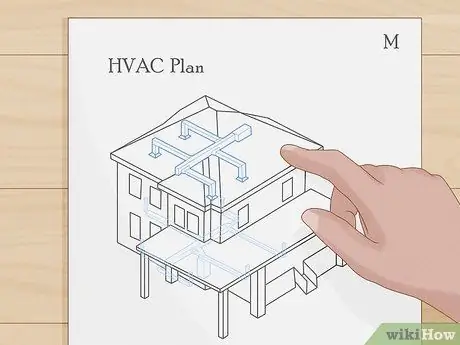
Step 3. Review the engineering drawings
The drawings of the technical systems are numbered with a " M.". These tables show the location of HVAC (heating, ventilation and air conditioning) equipment, ventilation ducts, refrigerant piping, as well as control wiring. Such guidance is rarely given for single family homes.
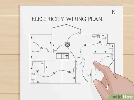
Step 4. Review the electrical system design
The drawings of the electrical system are numbered with a " AND". These tables indicate the arrangement of the electrical circuits, electrical panels, light points, control and socket points throughout the building, as well as RCDs, secondary panels and transformers, if present in the building.
- Some special tables of the electrical system project could refer to "auxiliary" details, which give indications on the power cables, on the diagrams of the electrical panels, which identify specific amperages and wiring for the automatic switches, and report information on type and diameter of electric cables and size of the holes.
- Some of this information may or may not be present in single-family residential projects.

Step 5. Review the environmental impact study
These tables indicate the protected areas of the construction site, soil erosion control plans and methods for preventing environmental damage during construction work. Tree protection techniques, geotextile fencing installation requirements, and temporary stormwater containment measures can be specified in the drawings.
The need for an environmental impact study depends on the environmental authority of your administration at local, regional or national level. Such a study may not be necessary, depending on the local authority responsible for single-family residences

Step 6. Note that all plumbing, electrical and air conditioning drawings are schematic
The measurements are rarely reported and it is the manufacturer's responsibility to organize the installation of the systems in order to satisfy the technical standards and architectural drawings. Make sure that the pipes are placed at the desired location of the sanitary ware. The same applies to electrical cables in reference to light points and sockets.
Part 4 of 4: Gain a deeper understanding of architectural drawings
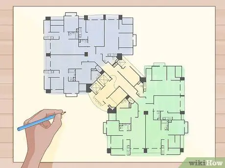
Step 1. Learn to draw the footprint of the building from the architectural plan
To do this, you need to locate the building element you are considering making. If you are plotting the location of the building, you must first look on the site plan for the location of existing buildings, structures or boundaries to have a reference point from which to determine the footprint of your building. Some floor plans simply provide the location of a coordinate grid using geographic coordinates, so you will need a "total station" to locate these points. Here's what you need to do to trace a building footprint from floor plans:
- Determine the footprint of your building on the construction site through the procedure mentioned above or by means of the measurements provided in the site plan. Measure the distance of the stations, preferably edges, on one side of the building, and use "control points" to verify the accuracy of your tracking. If you cannot determine exactly a building line, under certain conditions you can assume that the placement is correct and continue. This is widely accepted in cases where the construction site, being very large, allows a certain degree of tolerance, but in crowded sites the positioning must be exact.
- Determines the reference elevation. This could be an altitude related to a nearby road, or an altitude related to sea level. Your site plan or architectural plan should have a starting elevation reference height (for example, a manhole cover or a topographical landmark of known elevation) or a "elevation to existing level".
-
Use your floor plan to measure the location of each corner of the building, including irregular ones. Remember what precise construction element you are using for your layout. You can choose an "external wall line", a "foundation line" or a "column alignment", depending on the type of construction and which element is most suitable for subsequent measurements.
For example, if you are constructing a metal framed building having I-profile pillars that require "anchor bolts" to connect, you can start tracing your building from the axes of those pillars, while if you were constructing a framed building in wood on a monolithic foundation slab, the edge of the slab would be the best choice for the initial layout
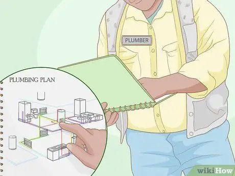
Step 2. The constructive elements that you will deal with in the course of the work can be described by more than one table
Plumbers use architectural floor plans to identify the walls in which to embed the connection pipes, then use the floor plumbing project to establish the type and size of pipes required for a particular user.
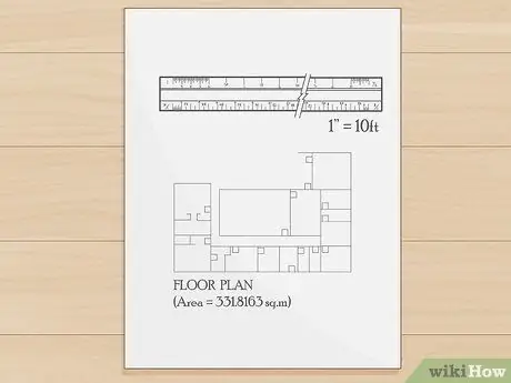
Step 3. Use the drawing scale when measurements are not provided
As a rule, the plans are drawn in "scale". For example, on the 1: 100 scale, one centimeter equals one meter (1 cm = 1 m), i.e. every centimeter of distance between two walls on the drawing is one meter in reality. A scalimeter makes everything easier, but make sure that the scale on the ruler matches that of the drawing. Some drawings or details are not to scale, and should be marked "out of scale".
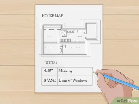
Step 4. Read all the notes on the drawing
Often a constructive element is characterized by special warnings that are expressed more easily in words than with the drawing, and the notes are the tool that the architect uses to illustrate them. At the edge of a table you may see a table of notes, with numbers (surrounded by a circle, a square or a triangle) that identify the position of the note on the drawing and the corresponding note in the margin of the sheet.
- Sometimes there may be one or more numbered drawing note tables that group all or most of the notes in an entire series of drawings. Many architects organize such numbered notes according to specific standards (such as those of the Construction Specifications Institute) that use 16 or more divisions by categorizing notes into classes.
- For example: the note "4-127" may refer to the type of masonry, as Class 4 concerns masonry. Note "8-2243" may refer to a window or door, as Class 8 applies to doors and windows.
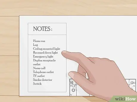
Step 5. Learn to recognize all the different types of lines that architects and engineers can use
For each group of tables there should be a specific "legend" that provides information on the abbreviations, symbols, and linetypes used.
- For example, in the projects of the electrical system, the section of the circuit that goes from the electrical supply panel to the first junction box can be highlighted or drawn with a thicker line than other sections, just as the visible holes can be indicated with a solid line while those undercut by a dashed or broken line.
- Since there are many different uses for a type of line that can indicate different types of wall, pipe, wiring or other, to understand their meaning you must consult the appropriate "legend".
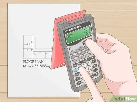
Step 6. The architect does not provide direct measurements of all building elements in the table, so you will need to be able to add various distances given for other elements of the drawing to get the total distance sought
An example could be the search for the midpoint of a toilet wall to determine the position of the drinking water connection pipe. You may need to add up the distance between a known landmark and the living room wall, then the distance to the hallway, then the distance across the bedroom, to the bathroom wall in question. The calculation could look like this: m 3, 40 + m 2, 75 + m 4, 80 = m 10, 95
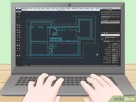
Step 7. Use your project's Computer Assisted Design (CAD) drawings
If you have a set of architectural drawings in electronic format, for example on CD, to view them you will need the original "cad" program with which they were created. "AutoCAD" is a popular but very expensive professional design program, so the designer will insert a viewer program on the disk that you can install on your computer to open the files, so you can see the design drawings on the screen, even if without. the complete program cannot manipulate the project or modify the drawings. However, many architectural firms are able to save their CAD or other electronic documents in the PDF format, which is usually the one used to send such documents by e-mail, so that you can easily open and consult them (but not alter them., since architects are responsible for the integrity of their work).

Step 8. Learn to handle project boards
These documents are often very large sheets, usually around 60cm x 85cm, and a complete project can consist of dozens or hundreds of sheets, which can also be bound. Allowing sheets to be torn from the binding, torn from clumsy handling, faded from excessive sun exposure, or left to wet in the rain can make it difficult to use.
Replacing these documents can cost hundreds of dollars, so try to protect them, and get a large, flat, protected work surface to unroll and consult

Step 9. Read the technical specifications of the tender specifications
The tender specifications are a printed document that describes in detail the specifications of the processes and materials envisaged by the project, as well as the methods of experimental tests, information on quality, and other useful information for the realization of the project. However, some architects include the specifications in the drawing sheets (to make sure they are not overlooked).
- The tender documents allow the architect to indicate the quality standards, materials, model numbers and other characteristics of the project. Even single-family residential buildings often have specifications. Traditionally, the specifications are organized according to numbered chapters, although this subdivision follows rather variable criteria.
- The articles of the specifications are numbered to allow architects to be able to refer on the drawings to the detailed wording of the specifications, in order to improve the coordination of the various activities.
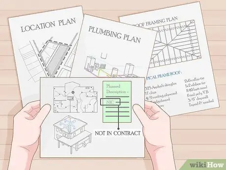
Step 10. Look for notes and symbols regarding "alternative offer items", "enhancement at Buyer's discretion" and "additions"
These notes may indicate parts of work that are present in the architect's drawings, but not necessarily in the contract with the construction company. Entries such as "by the client" mean that a certain element of the project must be carried out by the owner.
More specific terms such as "supply by the Customer", "installation by the Contractor" may indicate situations in which an element of the project is supplied by the owner but installed by the construction company. Read and make sure you understand all the wording in the project
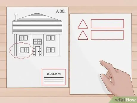
Step 11. Variants
Architects can submit variations, i.e. changes made to the project documents valid for the offer. Many architects reserve an empty space on the table, often in the lower right corner of the sheet, above the table number, for the revision list. Revisions are often numbered, surrounding the number with a triangle, octagon, circle, or other permissible symbol. Next to the revision number you will find the date and a short description of the revision. Then the relevant symbol will appear in the part of the drawing affected by the revision, next to a "revision cloud", represented by a lumpy series of arcs similar to that of comics, surrounding the modified part. This allows anyone to understand exactly what has been changed. In addition, the architect normally sends an e-mail to the owner and the tender participants at the same time summarizing the changes contained in each variant. It is then up to the different bidders to pass on information about these changes to their subcontractors and material suppliers.
Advice
- Make sure that the tables at your disposal are of "original size"; since the tables can also be printed in full size or in half size, with drawings of original size you can calculate the distances without relying on the graphic scale.
- If the drawings are half-sized, you will need to multiply the measurements made with the ruler by 2. Note that in most non-full-size drawings it is not indicated whether they are half (or other) size. Designs that are not exactly half the size of the original are sometimes called half size.
- Use triangular rulers or scalimeters to measure distances on drawings. The shape of this type of ruler, designed to offer minimal contact with the sheet, allows accurate positioning of the ruler and minimizes the possibility of error.
- While carrying out the work described in the project, keep a copy of the drawings on site to note any small changes with a pen or red pencil. Once the work has been completed, these drawings are usually returned to a designer in charge of drawing up graphic drawings, which are called "As-Built" ("As built"), which describe the work as it was created., recording the differences with respect to the project.
- Consult architectural design books or websites to get an idea of the typical appearance of lines, measurements, and floor plans.
Warnings
- Make sure you obtain all necessary building permits before starting any construction work. The local police, following an inspection, can block the work of any work that does not comply with the permits, and impose penalties.
- When in doubt about a measure or description in the project, ask the architect who drafted it rather than risk making a mistake that may be difficult to correct later.
- Know that, due to lack of space in the workplace, plumbing, electrical and plant engineering works cannot always be carried out simultaneously; therefore, to avoid interference, attention must be paid to the coordination of the various activities.


