Transformers are electrical components that connect at least two circuits together, allowing the passage of energy. Their function is to regulate the voltage of the circuits themselves, but in certain cases they can be damaged and prevent the operation of the devices connected to them. First you must identify some key characteristics of the component in your possession, for example the presence of visible damage, and differentiate the exit door from the entrance door; afterwards you shouldn't have much difficulty testing it with a digital multimeter. If you continue to have problems, read on to learn how to fix them.
Steps
Part 1 of 3: Identify the Basic Characteristics
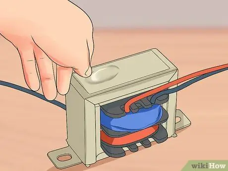
Step 1. Inspect it visually
A common cause of damage to this device is overheating, an event where internal cables operate at very high temperatures; it is usually triggered by a physical deformation of the transformer or by the area surrounding it.
If the outer box shows any bumps or obvious burn marks, do not test it but replace it
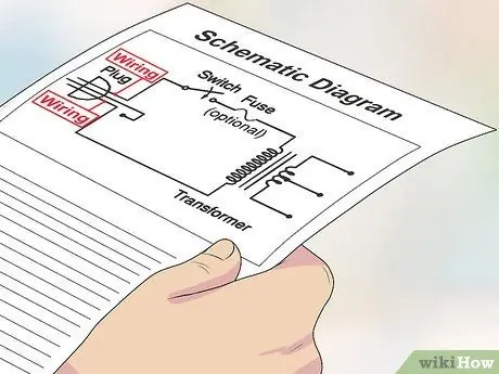
Step 2. Determine the wiring
It should be clearly labeled, but it's always best to get the circuit diagram to understand how it's connected.
The diagram should be available in the product information or on the manufacturer's website
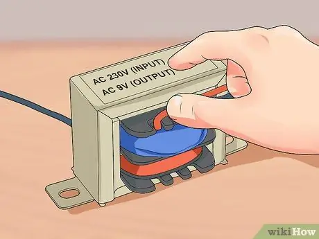
Step 3. Identify the entry and exit ports
The first electrical circuit is connected to the primary winding of the transformer and is the input port; the second circuit receives power from the transformer and is connected to the secondary winding, or output gate.
- The voltage that is applied to the primary should be indicated both on the body of the device itself and on the diagram.
- The one generated by the secondary should be indicated in the same way.
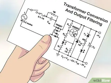
Step 4. Determine the output filtering
Generally, diodes and capacitors are connected to the secondary winding to convert the alternating electric current into direct current; this information is not shown on the label.
You can usually find the output filtering and conversion data on the circuit diagram
Part 2 of 3: Testing the Transformer with a Digital Multimeter
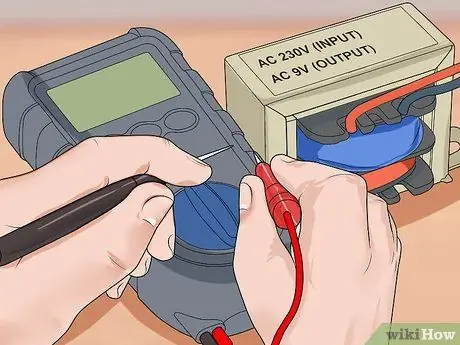
Step 1. Prepare to measure voltage values
Disconnect the power supply and remove the protective panels and boxes to gain access to the circuits containing the transformer. Get a digital multimeter (DMM) to proceed with the measurements; you can buy one at hardware stores, electronics stores, and home improvement centers.
In practice, you have to connect the instrument probes to the input lines to check that the primary winding has not suffered a short circuit; repeat the same procedure for the secondary
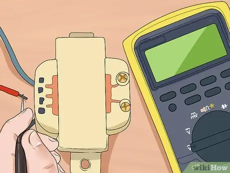
Step 2. Make sure the input power is adequate
Power up the circuit and use the multimeter set to alternating current to measure the primary winding. If you get a voltage value less than 80% of what you expected, the damage could be borne by the transformer or the circuit that supplies power. In this case:
- Disconnect the device from the input circuit and test it with the multimeter; if the potential difference values are those expected, the problem lies in the primary winding.
- If the input circuit voltage is less than the required value, the faulty element is not the transformer but the circuit.
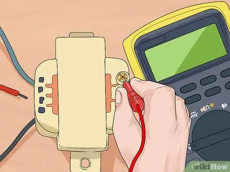
Step 3. Measure the output voltage
If no filtering or modulation is performed, always use the multimeter in alternating current mode; otherwise, set the meter to direct current mode.
- If you do not detect the output voltage you expected, the damage could be located in the transformer, filter element or modulation element; test these components separately.
- If you see no problem with these two elements, the problem lies in the transformer.
Part 3 of 3: Troubleshooting
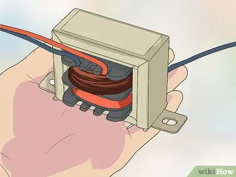
Step 1. Understand the source of the fault
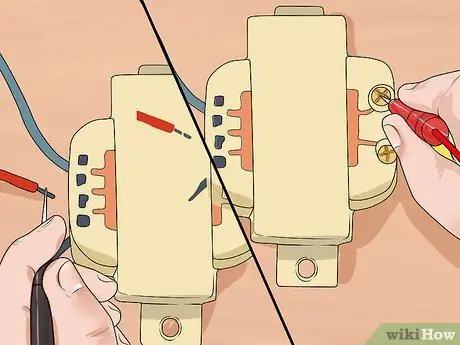
A transformer that does not work is usually a symptom of a problem located somewhere in the electrical circuit; usually this device lasts a long time and rarely burns out for no reason.
Step 2. Monitor the new transformer
If the damage that "shorted" the first device came from the circuit, the spare part is likely to burn out as well. After replacing the faulty one, carefully observe the new one to make sure it is not damaged, otherwise you will need to perform further tests.
When the appliance is overloaded, it often makes humming or clicking sounds; if you hear similar noises, disconnect the power to prevent the device from burning out
Step 3. Check the status of the external fuses, if necessary
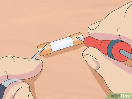
If the transformer is equipped with an internal fuse, the latter may not be present on the input circuit line; otherwise there should be such protection devices on the power line. Inspect them to make sure they are in perfect condition and replace any that are malfunctioning.
- If the fuses are blackened, melted or deformed, they are broken; remove them and replace them with spares
- In some cases it is not easy to understand if the fuse is in good condition. Test it with the multimeter by placing the probes at each end; if the current flows through it, it means that it works.
Step 4. Check for excessive wear of the secondary winding
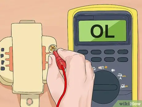
It can happen that this element absorbs too much energy causing a short circuit. If you have a transformer with multiple outputs and your multimeter reports an "OL" (overload) reading from the secondary, the secondary is likely to be bad.
- Check this by connecting the secondary winding to its circuit and use the multimeter to test the output lines. If the current strength data you got is higher than the transformer rating, the circuit is drawing too much power.
- Many devices have 3 A fuses; the nominal value of the current is printed on the luminaire itself, but you can also get it from the circuit diagram.
Step 5. Remove the input and output circuitry to locate the source of the problem
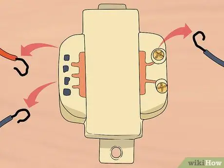
When dealing with inline fuses, you only have one output and one input; in this case the fault is located in one of the two circuits. If you are using more complex fuses, disconnect the inputs and outputs one at a time to identify the cause of the short.
Advice
- Early indications of a burning transformer are humming or snapping sounds.
- Do not assume that the primary and secondary winding of the appliance have the same ground connection, as this is often not the case; take this into consideration when taking measurements.


