Bridging an amplifier means combining the available channels so that they become a single channel that has half the load (expressed in Ohms) and, consequently, double the power. This type of setup is commonly used in car stereos, allowing you to drive a subwoofer via a very powerful mono signal.
Steps
Method 1 of 2: Bridge a 2 Channel Amplifier

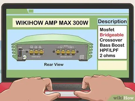
Step 1. Make sure your amp can be bridged
The adoption of this configuration should be indicated on the documentation supplied with the device or on the amplifier itself. If it is a used amplifier or if the documentation has been lost, go to the manufacturer's website to locate the technical specifications.
- When bridging an amplifier, the load resistance (measured in Ohms) is reduced by half, which can cause the equipment to overheat. Read carefully the instruction manual (or consult the manufacturer's website) to see if the amplifier, once connected to the speaker, can work with half the load expected for normal use.
- Most amplifiers have a small diagram near the channel terminals indicating which connectors to use for the bridged configuration. If your device appears to be unable to work with this type of configuration, do not bridge it for any reason. It is very likely that the internal components are already bridged, so making a second such connection would cause irreparable damage.
- Pay attention: if your equipment is a stereo amplifier (ie it amplifies both the input signals, left and right), bridging it means transforming it into a mono channel amplifier.

Step 2. Examine the structure of your equipment
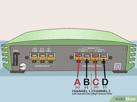
A two-channel amplifier should have 4 terminals: one pair (one positive (+) and one negative (-)) for channel 1 and one pair (one positive (+) and one negative (-)) for channel 2 Each of the terminals will be labeled with the following scheme:
-
Channel 1
- "A" (positive terminal)
- "B" (negative terminal)
-
Channel 2
- "C" (positive terminal)
- "D" (negative terminal)

Bridge an Amplifier Step 3 Step 3. Connect the amplifier to a single speaker
Connect the positive pole wire of the speaker to the terminal TO (the positive one of channel 1) of the amplifier, then proceed to connect the cable relating to the negative pole of the speaker to the terminal D. (the negative one of channel 2) of the amplifier. The connection must be made by unscrewing the relative screws of the amplifier terminals, inserting the copper cable between the two contacts of the terminal and tightening the appropriate screw. This way, the cable should be firmly connected to the amplifier.
- The cables coming from the loudspeaker are insulated by an outer plastic cover. You will need to remove a small part of it at the end (about 1-2 cm) in order to expose the copper electrical cable and be able to secure it to the terminal. To remove the insulation cover, use a pair of electrician's scissors or a suitable stripping pliers.
- This type of configuration allows you to combine the power normally destined for the two amplifier channels in order to double the output power.
Method 2 of 2: Bridge a 4-Channel Amplifier

Bridge an Amplifier Step 4 Step 1. Look at your amplifier
Just like in the first method of this guide, the first step is to figure out if your four-channel amplifier can be bridged. Take all necessary precautions by consulting the instruction manual or searching online based on the model of your device to be sure it can work in a bridged configuration.

Bridge an Amplifier Step 5 Step 2. Examine the structure of your equipment
A four-channel amplifier should have 8 terminals: each channel, from 1 to 4, must have a pair of terminals, one positive (+) and one negative (-). Each of the terminals will be labeled with the following scheme:
-
Channel 1
- "A" (positive terminal)
- "B" (negative terminal)
-
Channel 2
- "C" (positive terminal)
- "D" (negative terminal)
-
Channel 3
- "E" (positive terminal)
- "F" (negative terminal)
-
Channel 4
- "G" (positive terminal)
- "H" (negative terminal)

Bridge an Amplifier Step 6 Step 3. Connect the amplifier to the first speaker
Connect the positive pole wire of the speaker to the terminal TO (the positive one of channel 1) of the amplifier, then proceed to connect the cable relating to the negative pole of the speaker to the terminal D. (the negative one of channel 2) of the amplifier. As in the case of a two-channel amplifier, the connection must be made by unscrewing the relative screws of the amplifier terminals, inserting the copper cable between the two terminal contacts and tightening the appropriate screw. In doing so, the cable should be firmly connected to the amplifier.
After connecting the cables firmly, the first speaker will be connected to the amplifier

Bridge an Amplifier Step 7 Step 4. Connect the amplifier to the second speaker
To do this, follow the instructions in the previous step, but in this case remember to connect the cable relating to the positive pole of the second speaker to the terminal AND (the positive one of channel 3) of the amplifier; then proceed to connect the cable relating to the negative pole of the second speaker to the terminal H. (the negative one of channel 4) of the amplifier.
Advice
- Before attempting to make any connections, seek the advice of a professional audio installer or go to a center that performs this type of installation.
- Try to set a load for the amplifier that is slightly higher than the minimum resistance indicated. For example, assuming the amplifier can handle a minimum load of 2 Ohms, connect it so that it has to carry a load of 4 Ohms. Connecting it to a lower load could cause the amplifier to go into protection and shut down.


