Transistors are semiconductor devices that, depending on the conditions, allow or not the passage of current. They are widely used as switches or amplifiers. You can test the operation of a transistor using a multimeter that has the diode test functionality.
Steps
Method 1 of 4: Understand what transistors are
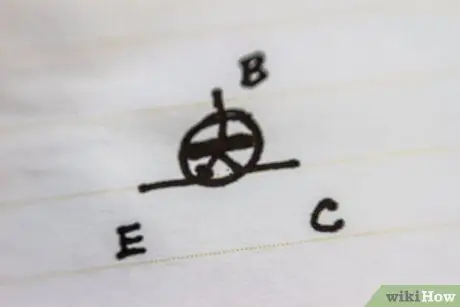
Step 1. A transistor is basically made up of two diodes having a common output
The common output is called the base, and the other two are called the emitter and collector.
- The collector receives a current from the circuit, but cannot make it flow through the transistor if the base does not allow it.
- The emitter sends current to the circuit, but only if the base allows the collector to let the current flow, through the transistor, towards the emitter.
- The base acts as a door. As soon as a weak current is applied to the base, the door opens and an intense current can flow from the collector to the emitter.
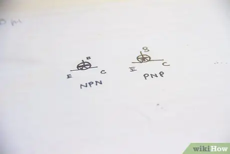
Step 2. Transistors can operate via bipolar junction or field effect, but, in both cases, there are two types
- NPN transistors employ a positive (P-type) semiconductor material for the base, and a negative (N-type) semiconductor material for the collector and emitter. In a schematic, an NPN transistor is represented with the arrow of the emitter pointing outwards (remember: "never inwards").
- PNP transistors, on the other hand, employ a negative (N-type) semiconductor material for the base, and a positive (P-type) semiconductor material for the collector and emitter. In a schematic, a PNP transistor is represented with the arrow of the emitter pointing inwards ("always inward" is the phrase to remember).
Method 2 of 4: Prepare the Multimeter
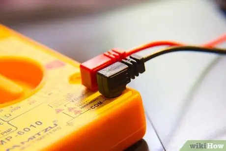
Step 1. Insert the probes into the multimeter
The black probe goes into the common terminal, and the red probe into the terminal with the diode test symbol.
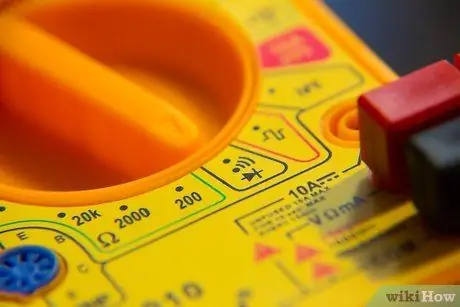
Step 2. Move the switch to the “diode test” mode
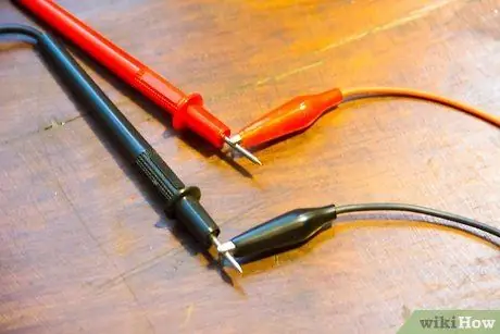
Step 3. Replace the probe tips with alligator clips
Method 3 of 4: Perform the test knowing how to distinguish Base, Emitter and Collector
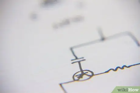
Step 1. Determine which of the terminals is the base, which the emitter and which the collector
The terminals are round or flat wires that come out from the bottom of the transistor. Some transistors report the identification of the terminals; in other cases you will need to determine, by consulting the circuit diagram, which of the terminals is the base.
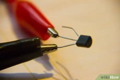
Step 2. Hook the clamp of the black probe to the base of the transistor
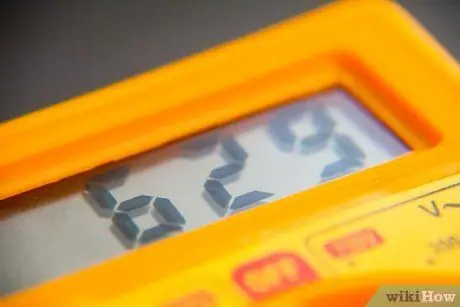
Step 3. Connect the red probe to the emitter
Read the multimeter's display and check if the detected resistance value is high or low.
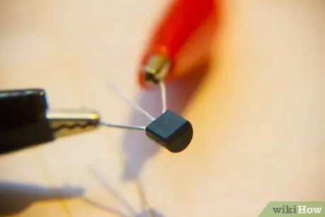
Step 4. Move the red probe to the manifold
The display should indicate the same resistance value read on the emitter.

Step 5. Remove the black probe and snap the red probe to the base

Step 6. Connect the black probe first to the emitter and then to the collector
Read the measured values, and compare them with the previous measurements.
- If the values read in the previous measurements were both high and now both are low, the transistor is functional.
- If the values read in the previous measurements were both low, while they are now both high, the transistor is functional.
- If the measurements made with the red probe did not detect the same value, or if the measurements made with the black probe did not detect the same value, or if the values did not change when changing the probe, then the transistor is faulty.
Method 4 of 4: Perform the test without knowing how to distinguish Base, Emitter and Collector
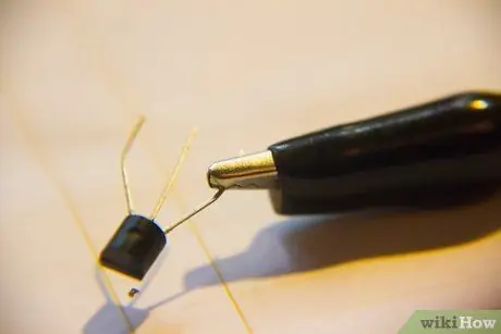
Step 1. Hook the black probe to one of the transistor terminals
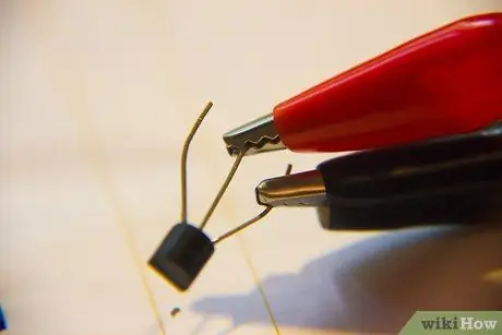
Step 2. Connect the red probe to the other two terminals
- If the display shows high resistance values for each of the two terminals, then you have found the base (and also a working NPN transistor).
- If the display shows two different values for the two terminals, then hook the black probe to a different terminal and repeat the test.
- If you have hooked the black probe to each of the three terminals and, in all cases, you have never detected high and equal resistance values on the other two terminals with the red probe, then the transistor is faulty or is of the PNP type.

Step 3. Remove the black probe and clip the red probe to one of the terminals

Step 4. Connect the black probe to the other two terminals
- If the display shows high resistance values for each of the two terminals, then you have found the base (and also a working PNP transistor).
- If the display shows two different values for the two terminals, then hook the red probe to a different terminal and repeat the test.
- If you have hooked the red probe to each of the three terminals and, in all cases, you have never detected high and equal resistance values on the other two terminals with the black probe, then the PNP transistor is broken.


