Thousands of designers around the world use AutoCAD to create visual representations of important projects. Buildings, bridges and cityscapes come to life in AutoCAD and allow engineers, customers and the public to better understand a certain project. AutoCAD is an essential visual communication tool for civil engineers.
The following instructions will tell you how to set an optimal set-up for your AutoCAD. This is crucial for producing a tidy and visually beautiful design. Read each step carefully before taking the required action.
Steps

Step 1. Open AutoCAD
The program can be found as an icon on the desktop, or can be found in the START menu in the lower left corner.
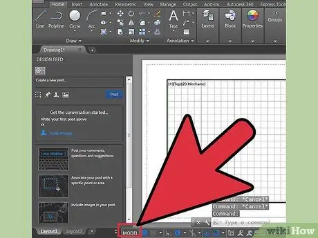
Step 2. Go to the modelspace
There are two modes in AutoCAD: modelspace and paperspace. The drawings must always be done in modelspace, while the dimensions that are added later must be represented in the paperspace. To switch between modelspace and paperspace, check the labels at the bottom of the screen. One indicates 'modelspace' and the other 'sheets' or 'layouts'. The 'sheets' or 'layouts' indicate the paperspace. If you are in modelspace, the screen background should be black. If you are in paperspace the background should be white.
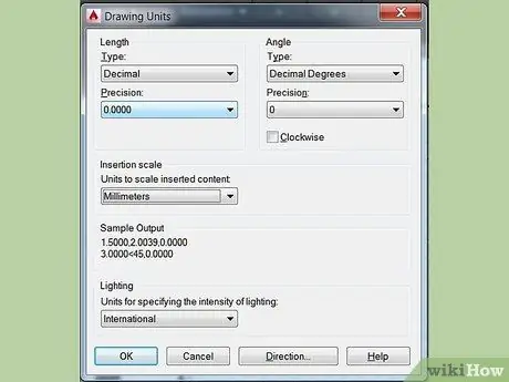
Step 3. Set the units
Engineers set units in different ways: feet, meters, etc. For greater accuracy and to eliminate confusion it is important that the drawing is done with the right units. To set the units, type 'UN' on the keyboard and then the 'ENTER' key. A dialog will open that will allow you to specify the type of units and their accuracy. The options for the unit type are: DECIMAL, SCIENTIFIC, ENGINEERING, ARCHITECTURAL, FRACTIONAL. The 'precision' section allows you to choose the number of decimal places for your dimensions. If you are doing a school project your teacher should have information regarding the specifics for the units.

Step 4. Select the toolbar you will use for your design
Mouse over an empty area at the top of the screen, near the toolbar. Right click and select AutoCAD; a long list should appear with several toolbars containing different commands. The most used in 2D AutoCAD drawings are DRAW, MODIFY, and OBJECT PROPERTIES. Select these and they should appear as pop-ups on your screen. Move them to the side to make room for the drawing. DRAW TOOLBAR: Contains normal drawing tools. MODIFY TOOLBAR: contains modification options. OBJECT PROPERTIES TOOLBAR: Contains style and color options.

Step 5. Start OSNAP
OSNAP, which refers to object snap, is a very useful property when drawing; allows you to see where the "end" and "middle" points of a line are, where is the tangent in a circle and other useful information. To activate the OSNAP function, press F3. To make sure that the OSNAP settings are active, click with the right mouse button on the 'OSNAP' icon located in the lower left corner of the screen; a dialog box will open. Click 'SELECT ALL' making sure that all OSNAP properties are active.
Method 1 of 2: Scaling a Design
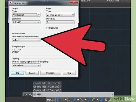
Step 1. Import or go to the Autocad drawing which is not to scale
It is okay if the Autocad drawing is not to scale, but if you know at least one length of it. Type "A" followed by the space bar to change units. Make sure the units are architectural and accuracy 5mm.
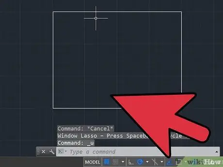
Step 2. Identify a line segment in the drawing whose length you know
It can be the length of a wall or that of a building. Longer lengths make Autocad scaling better. For example, it is not best to scale a design based on the width of a door or the length of a piece of furniture.
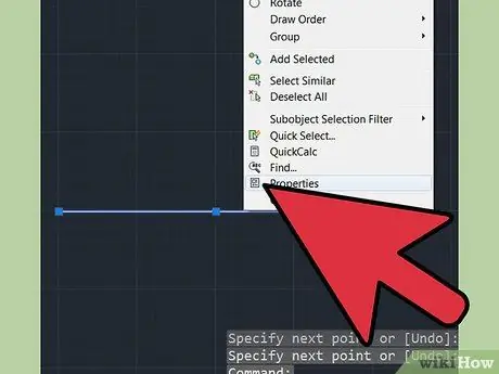
Step 3. Measure the length of the segment you chose in step 2
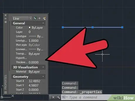
Click on the line, type "properties" followed by the space bar in the command line. Scroll down the window until you find the length of the line. Write down the number. You can also make a new line in the drawing to scale from if it is not present in the drawing, for example the length of a building.
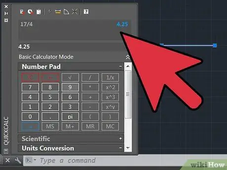
Step 4. Divide the length that the line should have by the length of the line in the drawing (actual length) / (length measured in the drawing)
You should get a decimal number. Write down this number.
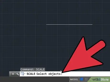
Step 5. Type "scale" in the command bar followed by the spacebar
Then select the entire AutoCad drawing and press the space bar. Then click any part of the design. By moving the mouse you will see that AutoCad will try to manually scale the drawing. Do not click a second time; instead, type the number you got in step 5 into the command bar. Then press the spacebar. The drawing should be carefully scaled.

Step 6. Check the line you measured in step 2 to make sure the scale is accurate
If it is close, but slightly off, you may not have included enough decimals in your scale calculation. Repeat steps 3-6 for more precise scaling. After a second pass, the AutoCad drawing should be carefully scaled.
Method 2 of 2: Scaling with Length Reference
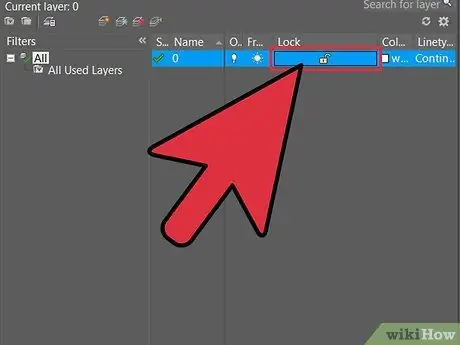
Step 1. Check the settings
Before scaling make sure all layers are ON and UNLOCKED.
Warning: you can use more or less the same procedure when you rotate an object by an indefinite angle

Step 2. Use the following commands:
- Command: Line Draw a line of the length you want to use (for example, you have an object in your drawing and you want it to be 100 units long, so draw a line 100 units long). This will be the reference length.
- Command: Scale Select the entire design, except the reference line, and press the spacebar.

Step 3. Select the base point
- Type "re" and press space.
- Take the first point and the end point of the object from the drawing, whatever you want along 100 units.
- Type "po" and press space.
Step 4. Take the first point and the end point of the reference line you drew
Step 5. Done
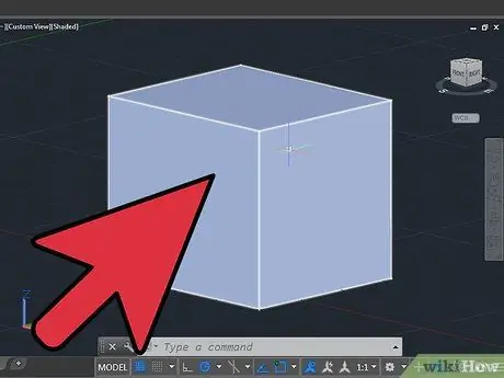
Instead of having to calculate and write the decimals, AutoCAD will now take care of it, and the result will be a perfectly scaled drawing.
Advice
-
The following is a list of the most used commands when making drawings in AutoCAD:
- Cancel - cancels a command. 'ESC'
- Undo - undoes the last command. 'CTRL' + 'Z'
- Erase - erase an object, line or other element. 'E' + 'ENTER'
- Circle - creates a circle with a specific radius. 'C' + 'ENTER' enter the length of the radius + 'ENTER'
- Line - creates a line of a certain length. 'L' + 'ENTER' enter line length + 'ENTER'
- Rectangle - creates a rectangle. 'REC' + 'ENTER' enter the dimensions + 'ENTER'
-
Trim - cuts a line at a previous intersection point. 'TR' + 'ENTER' selects the line to be cut + 'ENTER' selects the side of the line to be cut
Warning: a line must be intersected by another line in order to use the 'trim' command


