Capacitance is a scalar physical quantity that measures the ability of an object to store an electric charge, as occurs for example for capacitors, fundamental elements of electrical and electronic circuits. The unit of measurement of capacitance or electrical capacity is the farad (F). A capacitance of 1 farad is equal to that of a capacitor which, charged with an electric charge of 1 coulomb (C), has a potential difference between its plates equal to 1 volt (V). In real practice, the farad represents a very high electrical capacity, therefore submultiples are normally used, such as microfarad, i.e. 1 millionth of a farad, or nanofarad, i.e. 1 billionth of a farad. While very expensive instruments must be used to measure capacitance accurately, it is still possible to obtain a rough estimate of this information using a common digital multimeter.
Steps
Method 1 of 2: Remove Power to the Device
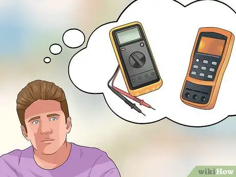
Step 1. Choose the instrument with which to perform the measurement
Often even cheap digital multimeters are equipped with the functionality (indicated with the symbol "- | (-") to measure the electrical capacity of a capacitor. Generally, instruments of this type are sufficiently accurate to allow to detect faults or malfunctions in the electrical and electronic circuits, but they are usually not accurate enough to make a precise measurement of capacitance. Digital multimeters of this type are quite accurate in measuring the electrical capacitance of most film capacitors, since they behave very much similar to ideal capacitors, which are used by the multimeter itself as a mathematical model to make the calculations related to the measurement. If in your specific case precision and accuracy are extremely important, consider using an LCR meter. they have a cost that can reach several miles aia of euros, but offer multiple accurate and precise methods for measuring the capacitance of a capacitor.
- This article focuses on using common digital multimeters. LCR meters are equipped with a specific instruction manual for each individual device.
- ESR ("Equivalent Series Resistance") meters can measure capacitors while installed in circuits, but cannot measure capacitance directly.
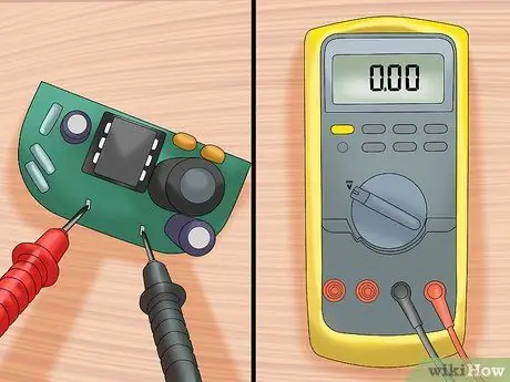
Step 2. Remove power from the circuit or device you are measuring on
To check for this condition, set up your multimeter to measure voltage. Place the two probes of the multimeter on the negative and positive pole of the section of the circuit that manages the power supply. If the power supply has been turned off correctly, the measured voltage should be 0 volts.
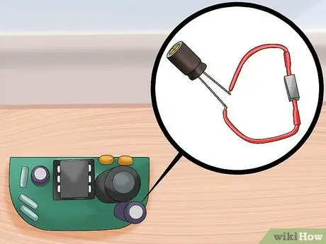
Step 3. Discharge the residual charge of the capacitor with extreme care
A capacitor is able to retain its electrical charge even for several minutes after it has been disconnected from the power supply, and in some (rare) cases even longer. To safely discharge a capacitor, connect a resistor to its terminals. However, make sure that the electrical component chosen as a resistor offers an electrical resistance suitable for the purpose:
- In the case of small capacitors, it is good to use resistors with a resistance of at least 2,000 Ω and a power of 5 watts.
- Larger capacitors, such as those found inside household appliances power supplies, camera flash circuits, or large electric motors, are capable of storing a very dangerous or even lethal electrical charge. the human beings. In this case, the supervision of expert personnel is recommended and the use of a resistor with an electrical resistance of at least 20,000 Ω and a power of 5 watts, to be connected using an electrical cable with a section of 12 mm2 capable of withstanding a voltage of 600 volts.
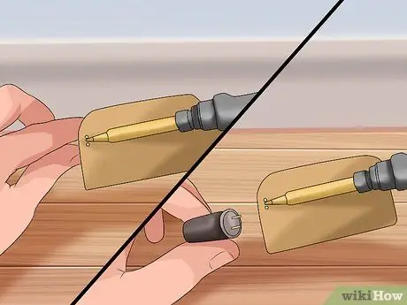
Step 4. Disconnect the capacitor under test
Taking measurements while the component is still installed in the circuit it is part of can give inaccurate results or can potentially damage other components. Remove the capacitor from the circuit very carefully. If necessary, resort to using a soldering iron to unsolder the capacitor terminals from the circuit to which it is connected.
Method 2 of 2: Take the Measurement
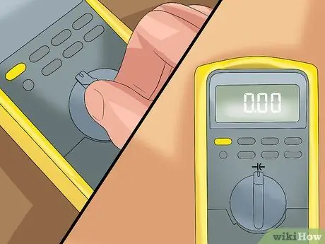
Step 1. Set up the multimeter so that it can measure capacitance
Most digital multimeters use a symbol similar to the following -|(- to indicate capacitance; move the device selector to the symbol shown. In some cases, a specific position of the multimeter's selector can refer to multiple operating modes; use the appropriate button to cycle from one function to another until the capacitance symbol appears on the screen.
If the instrument you are using is equipped with multiple capacitance measurement scales, choose the one that best suits the value you expect to detect (to get a rough estimate of this figure, read the code written on the external structure of the capacitor). Conversely, if you have only one multimeter setting available to measure capacitance, it means that the device will automatically detect and configure the full scale that best suits the situation
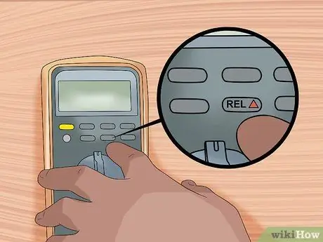
Step 2. If present, activate the "REL" mode (Relative mode)
If your multimeter has a "REL" button, press it while the measurement probes are separate from each other and not connected to the capacitor. The instrument will be "calibrated" so that the capacitance of the measuring probes of the multimeter cannot interfere with that of the capacitor under test.
- This step is only necessary for small capacitors.
- On some models of multimeters, this operating mode disables the automatic range selection.
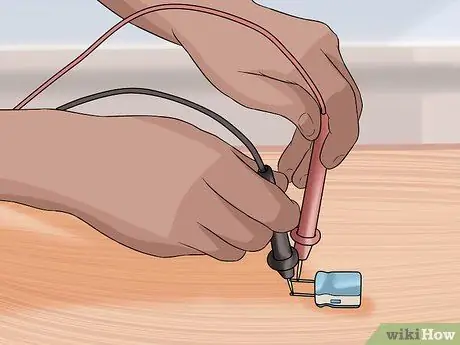
Step 3. Connect the multimeter's probes to the capacitor terminals
Note that electrolytic capacitors (which in most cases have a cylindrical shape) are polarized. If so, you will need to identify the positive and negative terminals before you can connect the multimeter's probes. This information will have little relevance for capacitance measurement purposes, but it is crucial to correctly insert the component within an electrical or electronic circuit. Look at the capacitor for any of the following indicators:
- A + or - placed next to the connection terminals.
- If one terminal is longer than the other, it means that the first is the positive pole.
- A small colored stripe next to a terminal is not a reliable indicator of polarity as different standards are adopted depending on the type of capacitor.
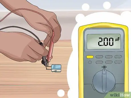
Step 4. Wait for the measurement value to be displayed
The multimeter will send an electric current to the capacitor to charge it, then it will measure the voltage (i.e. the potential difference) between the two terminals and use this information to mathematically calculate the capacitance. This procedure may take several seconds to complete, and while the measurement is in progress, the multimeter's buttons and screen may have longer response times than normal.
- If the "OL" symbol or the word "overload" appears on the instrument screen, it means that the capacitance of the capacitor under test is too large to be measured with the current multimeter. If possible, manually set a larger range or full scale. This can also be the result of the capacitor shorting.
- If the multimeter is able to automatically set the full scale, it will start using the smaller one and then increase it if it is reached. Before the final measurement value is shown, the "OL" symbol may appear multiple times on the screen.
Advice
- Humans also behave electrically like capacitors. Whenever you rub your feet on a carpet, make contact with a car seat or comb your hair, you are charging your body with static electricity. The total capacitance of your body depends on its size, posture and proximity to other electrical conductors.
- Most capacitors have an identification code that declares their capacitance. Compare this information with the value you measured with the multimeter to find out if it has reached the maximum charge.
- Analog multimeters (which feature an indicator with a moving needle instead of a liquid crystal display) are not actively powered, so they cannot send a current to the capacitor to test its operation. You can use an analog multimeter to find out if a capacitor is broken, but not to accurately measure its capacitance.
- Some multimeters have special cables for use only for checking capacitors.


