Resistance is a measure of the difficulty electrons face when passing through a particular object. It can be compared to the concept of friction that develops on a moving object or displaced on a surface. Resistance is measured in ohms; one ohm equals one volt of potential difference divided by one ampere of current. Resistance can be measured with either a digital or analog multimeter or ohmmeter. Analog devices typically feature a needle that indicates the measurement on a scale, while digital devices provide a numerical measurement on a display.
Steps
Method 1 of 3: Measure Resistance with a Digital Multimeter
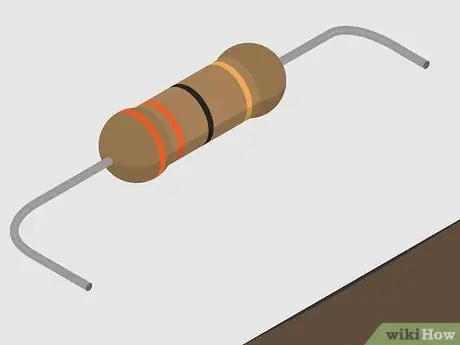
Step 1. Choose the object whose resistance you want to know
For accurate values, test the resistance of a single component. Disassemble it from the circuit or test it before installing it. If you measure while the resistor is still plugged into the circuit, you will get inaccurate readings due to the presence of the other elements.
- For example, you could test the resistance of switches, relays, or motors.
- If you are testing a circuit or even just unplugging a component, make sure the power is off before continuing.
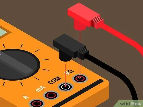
Step 2. Insert the probes into the correct control slots
Most multimeters have two probes, one black and one red. However, there are different control slots, depending on the value that needs to be measured: resistance, potential difference or current intensity. In general, the correct slots for the resistance are marked one with the writing "COM" and the other with the Greek letter omega (Ω) which represents the "ohms".
Insert the black terminal into the slot labeled "COM" and the red terminal into the slot labeled "ohm"
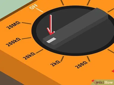
Step 3. Turn on the multimeter and select the measurement range
The resistance of a component can range from ohms (1 ohm) to megohms (1,000,000 ohms). To get an accurate reading you need to set the meter to the right order of magnitude in relation to the resistor. Some DMMs set up automatically, while other models need to be changed manually. If you have a vague idea of the order of magnitude of the component resistance, then proceed to setting the multimeter; if you have any doubts, you will have to proceed by trial and error.
- If you don't know the range the resistance is in, start with an intermediate setting, typically 20 kiloohm (kΩ).
- Touch the end of the component with one probe of the instrument and rest the second probe on the opposite end.
- 0, 00 or OL or the resistance value may appear on the screen.
- If the reading is zero, then it means that you have set an excessive order of magnitude and that you need to lower it.
- If your monitor says "OL" (which stands for overload in English), then the order of magnitude is too low and you need to increase it. Test the component again with the new setting.
- If you can read a specific number, like 58, then that is the component resistance value. Remember what unit of measurement you are considering. If you are using a digital multimeter, a symbol should appear in the upper right corner of the display reminding you of the order of magnitude you are using. If you see the "kΩ" symbol, it means that the resistance of the element is 58 kΩ.
- When you've found the correct range, try lowering it once more to get more accurate measurements. You should use the lowest possible setting for very accurate results.
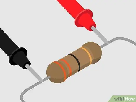
Step 4. Touch the terminals of the multimeter to the ends of the component under test
Just as you did earlier to find the order of magnitude of the resistance, tap the item with the instrument's probes. Wait for the values to stop increasing or decreasing and note the number that appears on the display. This indicates the resistance of the component.
For example, if you get a reading of 0.6 and you can see the MΩ symbol in the upper right corner, then the component resistance is 0.6 megohms
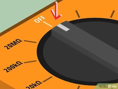
Step 5. Turn off the multimeter
When you have finished all measurements, turn off the meter and unplug the probes before storing.
Method 2 of 3: Measure Resistance with an Analog Multimeter
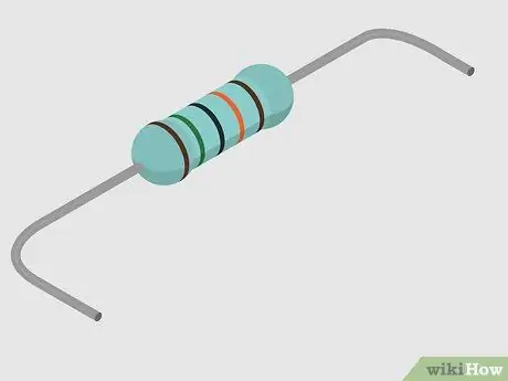
Step 1. Choose the object whose resistance you want to know
To get accurate readings, consider only one component individually. Unmount it from the circuit or test it before connecting. If you measure the resistance of a component without removing it from the circuit, you will get inaccurate readings, affected by the presence of other elements.
- For example, you could test a switch or motor.
- If you are testing a circuit or just disassembling a component, remember to turn off the power before proceeding.
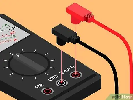
Step 2. Insert the probes into the correct control slots
Most multimeters have two probes, one black and one red. However, there are different control slots, depending on the value that needs to be measured: resistance, potential difference or current intensity. In general, the correct slots for the resistance are marked one with the writing "COM" and the other with the Greek letter omega (Ω) which represents the "ohms".
Insert the black probe into the slot labeled "COM" and the red one into the slot with the "ohm" symbol
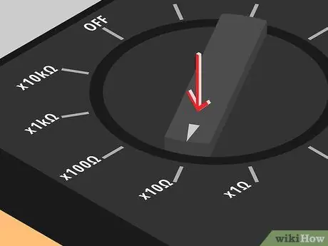
Step 3. Turn on the tool and select the size order
Component resistance can be in the order of ohms or megohms (1,000,000 ohms). To get accurate readings, it is important to set the meter to the correct range for the component. If you have a general idea of the order of magnitude, then you can continue with the setting, otherwise you will have to proceed by trial and error.
- If you don't know the order of magnitude, start with an intermediate range, typically 20 kiloohm (kΩ).
- Touch one end of the component with one probe and the opposite end with the second probe.
- The needle of the instrument will move along the graduated scale and stop at a specific point indicating the resistance of the element.
- If the needle moves past full scale (usually to the left), then you need to increase the order of magnitude you set the meter to, reset the multimeter to zero and try again.
- If the needle moves all the way to the right, below the "zero" level, then you have to decrease the order of magnitude, reset the meter and try again.
- Analog multimeters must be reset or zeroed each time the order of magnitude is changed and before testing the component. To do this, simply put the probes in contact with each other to create a short circuit. Make sure the needle is at "zero" when changing the order of magnitude or zeroing the meter after joining the probes.
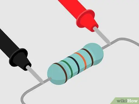
Step 4. Join each probe with one end of the electronic component you want to check
Just like you did earlier to set the order of magnitude, tap the ends of the resistor with the probes. The graduated scale of the instrument increases from right to left. The right side corresponds to zero and the left side goes up to 2 kΩ (2000 ohms). There are several scales on an analog multimeter, so be sure to read the one indicated by the Ω symbol increasing from right to left.
As the scale goes up, it indicates higher and higher values, whose reference marks are closer and closer. For this reason, it is essential to set the instrument with the correct order of magnitude otherwise you will not get accurate readings
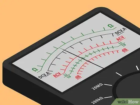
Step 5. Read the resistance value
When the probes make contact with the resistor, the needle moves to an intermediate point between zero and full scale. Be sure to use the ohm scale and note the number indicated by the needle. This represents the resistance of the component.
For example, if you have set the multimeter to 10 ohms and the needle stops at number 9, then the component resistance is 9 ohms
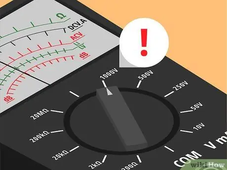
Step 6. Set the potential difference to the maximum range
When you have finished your readings, you need to properly store the multimeter. If you set it to the maximum voltage range before you turn it off, you can be sure it won't be harmed if someone uses it without checking the order of magnitude. Turn off the meter and disconnect the probes before putting it away.
Method 3 of 3: Run the Test Successfully
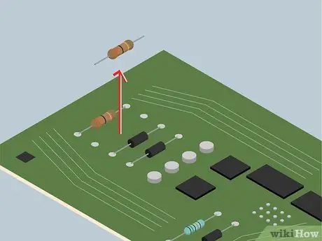
Step 1. Check the resistance of the individual components and not the entire circuit
If you test a component that is still connected to the circuit, you will get inaccurate values, because the multimeter will also detect the resistance of the other connected elements. However, sometimes it is necessary to measure the resistance of components in a circuit.
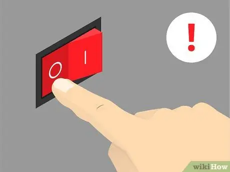
Step 2. Proceed to test only after disconnecting the power
If current flows through the circuit, inaccurate readings are obtained, as an increase in current generates an increase in resistance. Furthermore, the potential difference of the circuit could damage the instrument (for this reason it is not advisable to test the resistance of a battery).
Any capacitors in the circuit whose resistance are to be measured should be discharged before testing. Discharged capacitors are able to absorb some of the multimeter's current and create momentary fluctuations in the results
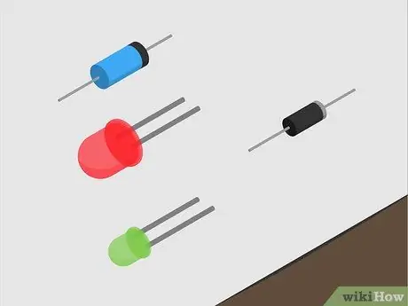
Step 3. Check the diodes in the circuit
These only conduct electricity in one direction; for this reason, within a circuit with diodes, by changing the position of the multimeter probes, different values are obtained.
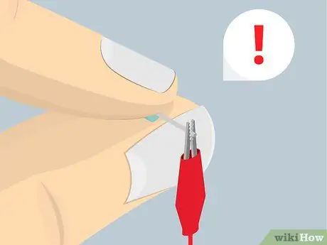
Step 4. Watch your fingers
Some resistors and components need to be kept in contact with the multimeter's probes. If you touch these elements or the probes with your fingers, you can cause inaccurate measurements because the body is able to absorb some of the energy of the circuit. This is not a problem when using a low voltage multimeter, but it could become a problem when using a high voltage meter.
One way to prevent your hands from touching components is to transfer them to an "experimental board" to test their strength. You can also use alligator clips as multimeter probes, so they don't detach from the resistor under test
Advice
- The accuracy of a multimeter depends on the model. The very cheap ones are accurate within a 1% margin of error. If you want a better tool, know that you will have to spend more.
- You can tell the resistance level of a resistor by the number and color of the bands that are printed on it. Some resistors have a 4-band system, while others follow a 5-based criterion. A band is used to represent the level of accuracy.


