A tester is one of the most useful tools for checking home power lines, if used correctly. Before using a tester for the first time, you will need to learn how to set it up correctly and test it on a low voltage circuit, as a home use device.
This article describes how to use the voltage measurement tester. You may also be interested in using a multimeter to measure current and resistance.
Steps
Part 1 of 3: Set Up the Device
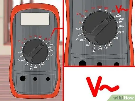
Step 1. Set up the tester to measure voltage
Most voltage measuring devices are in fact multimeters, capable of measuring different aspects of an electrical circuit. If your tester has a knob with different settings, follow these instructions to set it up:
- To measure the voltage of an AC circuit, set the knob to V ~, ACV or VAC. Household electrical circuits usually run on alternating current.
- To measure the voltage of a DC circuit, choose V-, V ---, DCV or VDC. Batteries and portable electronic equipment usually run on direct current.
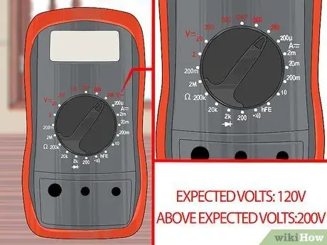
Step 2. Select a range greater than the maximum expected voltage
Most testers have several voltage options, so you can change the sensitivity of your device to get a correct measurement and avoid damaging it. If you have a digital meter that does not have an option to determine the range, this means that the device can automatically detect it and set itself accordingly. If not, follow these steps:
- Select a setting higher than the maximum expected voltage. If you have no idea what that might be, select the highest setting to avoid damaging the tester.
- Batteries for home use usually have a label indicating the voltage, typically 9V or less.
- Car batteries should have a voltage of around 12.6V when fully charged and with the engine off.
- Wall sockets usually have a voltage of 240 Volts in most countries, but 120 Volts in the United States and other countries.
- mV means millivolts (1/1000 V), sometimes used to indicate minimum settings.
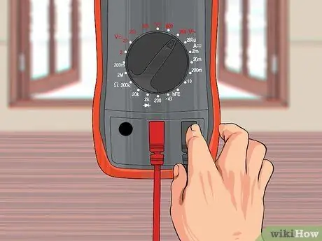
Step 3. Insert the test leads
The tester has two test leads, one red and one black. Each has a metal probe on one end and a metal jack on the other, to be inserted into the appropriate holes on the tester. Connect the jacks as follows:
- The black test lead goes into the "COM."
- When measuring the voltage, insert the red test lead into the hole V. (but there may be other symbols). If there is no hole labeled V, choose the one marked with the smallest number or with but.
Part 2 of 3: Measure the Voltage
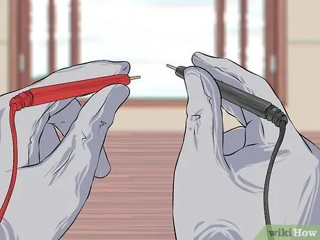
Step 1. Hold the tips in your hands so you are safe
Do not touch metal probes when they are connected to a circuit. If the insulation looks worn, use electrically insulated gloves or buy replacement test leads.
The two metal probes must never touch each other when connected to a circuit; otherwise many sparks could develop
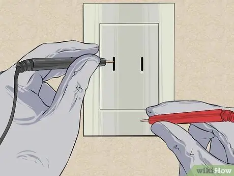
Step 2. Put the black test lead in contact with a part of the circuit
Check for voltage in a circuit by connecting the test leads in parallel. In other words, you will touch with the probes two points of a closed circuit, with the current flowing through it.
- If you are measuring the voltage of a battery, connect the black test lead to the negative pole.
- In a wall outlet, insert the black test lead into the ground hole.
- As soon as possible, release the black test lead before continuing. Often this is equipped with a protuberance that allows it to remain attached to the socket.
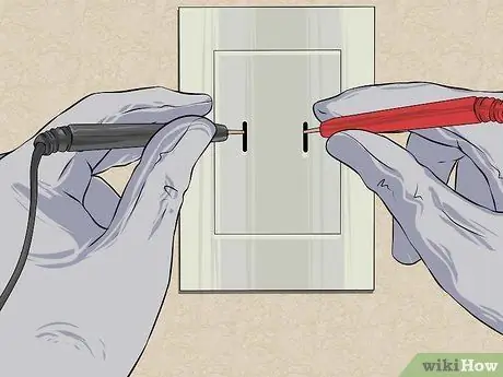
Step 3. Put the red test lead in contact with another part of the circuit
This will complete the parallel circuit and allow the tester to view the voltage.
- With a battery, connect the red test lead to the positive pole.
- In a wall outlet, insert the red test lead into the phase hole.
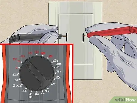
Step 4. Increase the interval if you get an "overload" error
Immediately increase the measurement range to a higher level if you get any of the following results, to avoid damaging the device:
- The digital display shows "OL," "overload" or "1." Note that "1V" is a correct value that you shouldn't worry about.
- The analog hand moves to full scale at the opposite end.
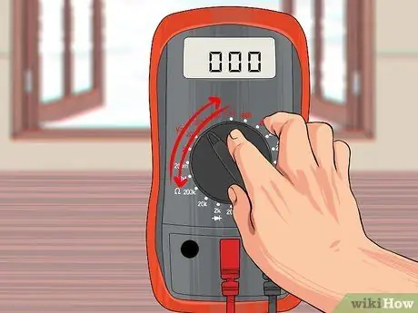
Step 5. Adjust the tester if necessary
You may need to make adjustments if the tester's display shows a reading of 0V or is not showing any readings, or if the hand of an analog tester does not move or just moves. If you're not getting any readings, try one of these steps, in order:
- Make sure both probes are connected to the circuit.
- If you are measuring a DC circuit and you are not getting any results, look to see if your device has a switch or knob with the indications DC + and DC- and, if there is, move it to the other position. If your device does not have this interruption, try reversing the placement of the red and black test leads.
- Reduce the measurement range by one unit. Repeat as necessary until you get a realistic measurement.
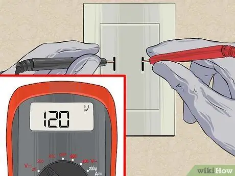
Step 6. Read the result
A digital meter will clearly display the voltage on its electronic display. An analog tester is a little more difficult to use, but not too much once you get the hang of it. Read on to learn how to use it.
Part 3 of 3: Reading an Analog Tester
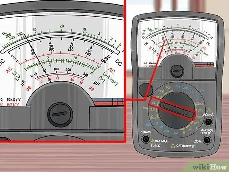
Step 1. Identify the voltage scale on the tester face
With the tester knob, select a corresponding setting. If there is no exact match, read with a scale that is a multiple of the one you set.
For example, if your tester is set to DC 10V, look for a DC scale with a maximum reading of 10. If not available, look for one with a maximum of 50
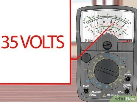
Step 2. Estimate the hand position based on neighboring numbers
It is a linear scale, just like a ruler.
For example, a hand that points midway between 30 and 40 indicates a reading of 35V
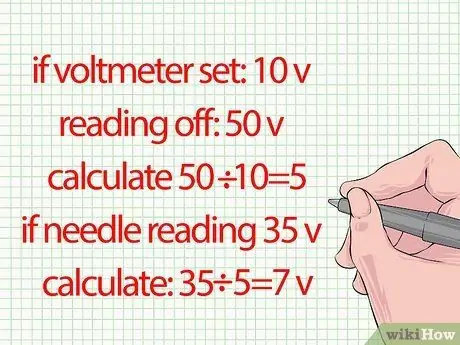
Step 3. Divide the result obtained from the reading if you are using a different scale
Skip this step take the reading with a scale that exactly matches the tester settings. If not, correct the reading by dividing the maximum scale value by the tester center knob settings.
-
For example, if your tester is set to 10V, but taking a reading with a 50V scale, calculate 50 ÷ 10 =
Step 5.. If the needle points to 35V, the correct reading is 35
Step 5. = 7V.


