It seems that the monitors and displays of a multimeter, for an inexperienced person, speak a language of their own. Even those who often work with electrical circuits sometimes need some advice when first using a new tool with an uncommon nomenclature. Fortunately, it doesn't take long to understand the abbreviations, learn how to read the scale, and quickly get back to your work.
Steps
Part 1 of 3: Reading Settings
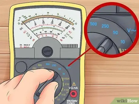
Step 1. Check the DC or AC voltage
Typically the letter V. indicates voltage, a wavy line indicates alternating current (which is normally found in homes), while a straight or dotted line indicates continuous current (mainly found in batteries). The lines are present near or above the letter.
- Settings for controlling the voltage of an alternating current (AC) circuit are usually indicated with: V ~, ACV or VAC.
- Regarding a direct current (DC) circuit you will find: V-, V ---, DCV or VDC.
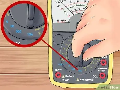
Step 2. Set up the multimeter to measure the intensity of the current
This magnitude is measured in amperes, the abbreviation of which is TO. Also in this case you have to choose between AC or DC current according to the circuit you need to control. Analog multimeters are usually unable to measure amperage.
- A ~, ACA And AAC are the abbreviations that indicate the setting for measuring the intensity of alternating current.
- TO-, TO---, DCA And ADC are the abbreviations that indicate the setting to measure the intensity of the direct current.
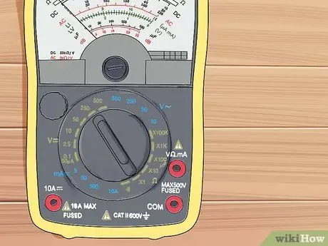
Step 3. Identify the resistance settings
This is indicated by the Greek letter omega Ω and the unit of measurement are ohms. In older multimeters, it was indicated by the letter R. (Resistence).

Step 4. Use the DC + and DC- settings
If your model provides it, use the DC + setting when testing a direct current. If you get no reading and you suspect that the positive and negative terminals are connected incorrectly, switch to DC- to correct this without having to swap the wires.

Step 5. Understand the other symbols
If you are not sure why there are so many settings for voltage, amperage or resistance, read the "Troubleshooting" section for more information. Most of the tools, in addition to the basic functions listed so far, also have additional configurations. If several indications are placed near the same setting, it means that they can work simultaneously or you need to check the manual.
- ))) or another similar series of parallel curved lines, indicate "the current test", that is, if the flow of electricity flows in the circuit. With this kind of setting, the instrument emits a beep if the two probes are electrically connected.
- An arrow pointing to the right with a cross that crosses it indicates the "diode test" which allows you to understand if the unidirectional electrical circuits are connected.
- Hz stands for Hertz, the unit of measurement of frequency for alternating current circuits.
- -|(- indicates the function for the electrical capacity.
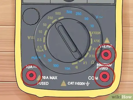
Step 6. Read the door labels
Most multimeters have ports or holes. Sometimes they are indicated with symbols that correspond to those described above. If the symbology is unclear, follow these guidelines:
- The black probe must always be connected to the port indicated with COM, also called "earth". The other end of the probe must always be fixed to a negative terminal.
- When measuring voltage or resistance, the red probe should be plugged into the port with the smallest measurement indicated (most of the time but indicating milliamps).
- When measuring the current, the red probe must be inserted into the port indicating the current intensity you expect. Typically, those for low intensity circuits have a fuse set to 200mA, while those for high intensity circuits have a 10A.
Part 2 of 3: Analog Multimeter
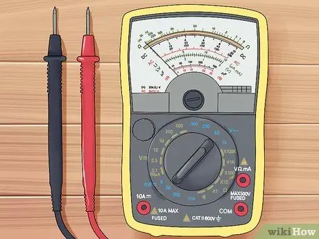
Step 1. Find the ladder
Analog models behind a glass window have a needle that moves to indicate the reading. Usually, on the background behind the needle, three arches are drawn with three different scales that are used, each, for specific purposes.
- The scale marked with Ω indicates the resistance. Usually it is the largest one, which occupies the outermost arch. Unlike the others, it has an initial value of zero in the left end.
- The "DC" scale is dedicated to the voltage for direct current.
- The "AC" scale indicates the voltage of the alternating current.
- The arc indicated with "dB" is the least used, at the end of this section you will find a brief description.
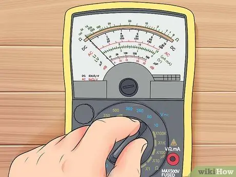
Step 2. Adjust the full scale for the voltage to the values you expect to obtain
Look carefully at the “DC” and “AC” arcs. There should be several rows of numbers under the scale. Check which range you have selected on the device (for example 10V) and look for the corresponding indication near this series of numbers on the arcs. This is the scale you need to consider for reading.
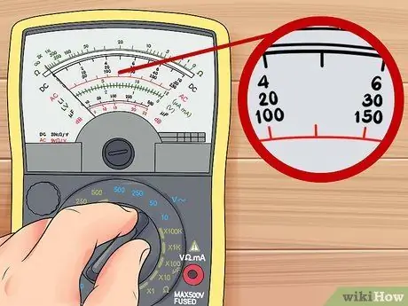
Step 3. Evaluate the range of values you plan to obtain
The volt scales of an analog multimeter work like a normal ruler. The resistance scale is logarithmic, which means that each segment of equal length indicates a varying difference in values, depending on where you are on the scale. The lines between two numbers indicate a constant subdivision. For example, if you find three lines between the value "50" and "70", then you know they represent the numbers 55, 60 and 65, although the segments may appear to be of different lengths.
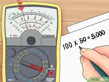
Step 4. Multiply the resistance reading on an analog multimeter
Check the scale settings your instrument has been adjusted to. These should give you a number to multiply the reading by. For example, if the multimeter reads R x 100 and the needle indicates 50 ohms, then you know that the real resistance is 100x50 = 5000 ohms.
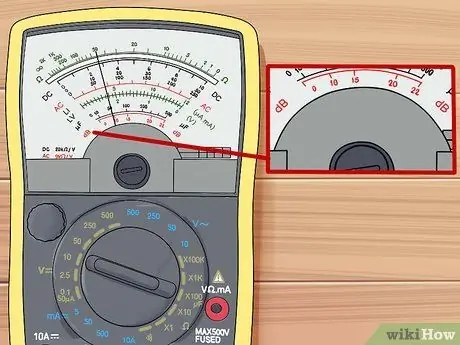
Step 5. Let's tackle the dB scale
This indicates the decibels and is located on the innermost arc of the instrument. To use it you need a minimum of training. It is a logarithmic scale that measures the transformation ratio (also called gain or loss). The standard dBv scale in the United States defines 0dBv as 0.775 volts measured on a resistance of 600 ohms, but there are also dBu, dBm, and dBV scales (with a capital V) to consider.
Part 3 of 3: Troubleshooting
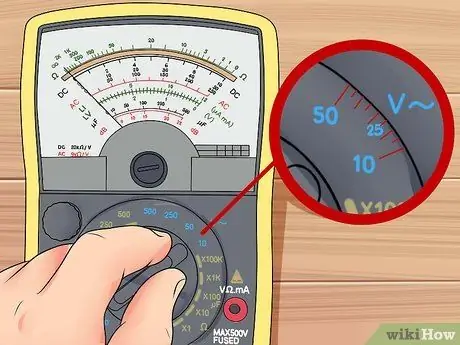
Step 1. Set the full scale
Unless you are using a multimeter that sets itself automatically, each reading mode (voltage, amperage and resistance) has several functions to choose from. This is the full scale you should decide before connecting the meter to the circuit. Start by setting the instrument to the highest setting closest to the expected reading. For example, if you plan to get a reading of 12 volts, set the multimeter to 25V and not 10V (assuming these are the two settings closest to the value you think you are getting).
- If you have no idea of the reading you will get, then select the maximum setting to avoid damaging the instrument.
- The other functions are less likely to ruin the multimeter, but always select the resistance to minimum and never go below 10V for the voltage.
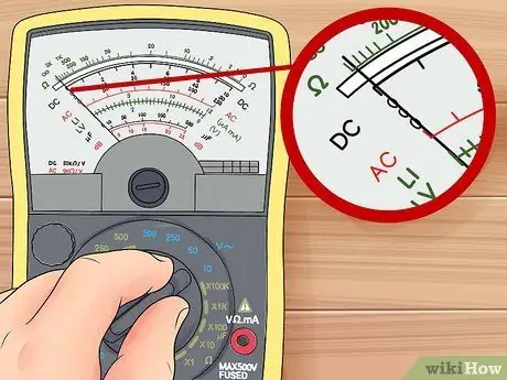
Step 2. Adjust the "out of scale"
On digital instruments you will find abbreviations such as "OL", "OVER" or "overload", which means that you have to set a higher full scale; readings very close to zero indicate that you need to lower the full scale if you want to be more accurate in your measurement. As for analogue instruments, an immobile needle indicates that you need to lower the full scale. If, on the other hand, the needle immediately clicks to the maximum, then you must select a larger full scale.
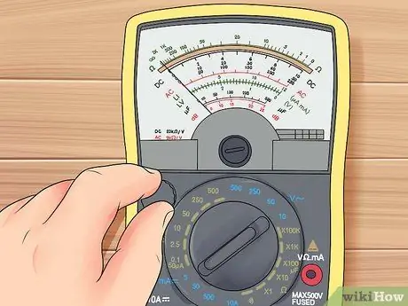
Step 3. Before measuring the resistance, disconnect the power supply
Lower the switch or remove the batteries from the circuit to make sure you get an accurate reading. The multimeter emits a flow of current to measure resistance; if there is other current in the circuit, you would get false values.
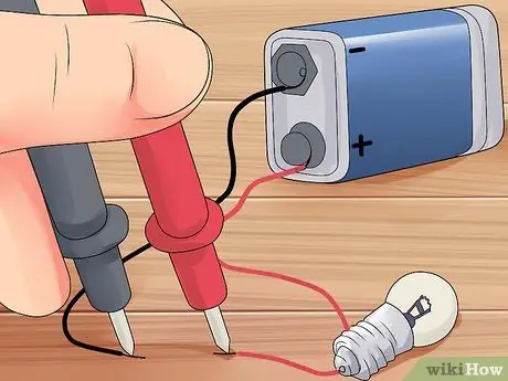
Step 4. Measure the current in series
To do this you have to form a circuit that includes the multimeter as an element "in series" with the other elements. For example, disconnect a cable from the battery terminal and connect it to one probe of the instrument while the other is fixed to the battery itself to close the circuit again.
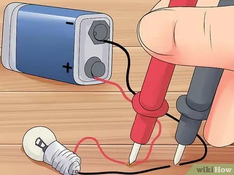
Step 5. Measure the voltage in parallel
Voltage measures the difference in electrical potential in a part of the circuit. If this is closed and passed through by electricity, the multimeter should have two probes to be connected in two different points of the circuit to connect the instrument "in parallel".
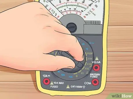
Step 6. Calibrate the ohms on an analog meter
This kind of multimeter has an extra setting that allows you to adjust the resistance scale (typically indicated with Ω). Before proceeding with the resistance reading, connect the two probes together. Turn the settings knob until the needle moves to zero and then move on to the actual test.
Advice
- If there is a mirror behind the needle of an analog instrument, tilt the multimeter to the right and left so that the needle itself overlaps with its reflected image. This will allow you an accurate reading.
- If you are having trouble with your digital multimeter, check its manual. By default the display shows numbers, but you can set it to show graphs or other types of information.
- If the needle of the analog multimeter marks a negative measurement it is likely that you are using the positive and negative connectors incorrectly. Reverse them and try again, you should get a correct reading.
- When you measure the voltage of the alternating current, at first the value will fluctuate, but it will stabilize allowing you an accurate reading.


