The PC power supply device costs around € 30, but a proper laboratory power supply can cost over € 100! Instead, just convert an inexpensive ATX power supply to obtain a phenomenal laboratory power supply with excellent current delivery, short-circuit protection and a fairly rigid voltage regulation on the 5V line.
Works on most power supply units, other lines are not regulated.
Steps
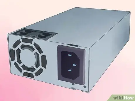
Step 1. To find an ATX power supply, search online or go to a computer store
Alternatively, you can disassemble an old computer and remove the power supply unit.
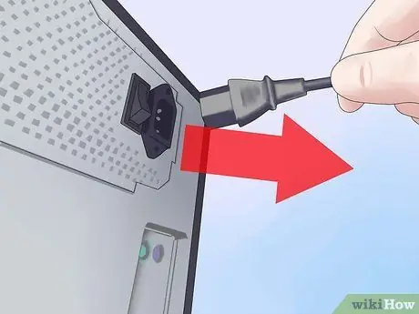
Step 2. Unplug the power cord from the socket and turn off the power supply using the switch (if present)
Make sure you are not grounded so that any remaining voltage does not pass through your body to discharge to ground.
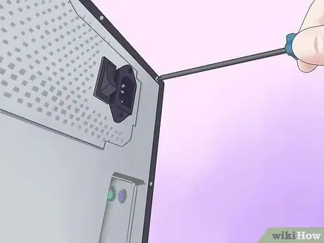
Step 3. Remove the screws that secure the power supply to the PC case and pull it out
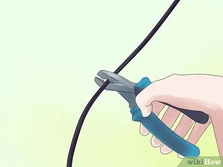
Step 4. Cut the connectors
Leave a few inches of wire on the connectors so you can reuse them later for other projects.
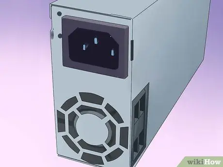
Step 5. Fully discharge the power supply by leaving it unplugged for a few days
Some suggest connecting a 10 Ohm resistor between the red and black wire. However, this method only guarantees the discharge of low voltage capacitors on the output - a very dangerous thing! High voltage capacitors could remain charged, resulting in dangerous, if not lethal, capacitors.
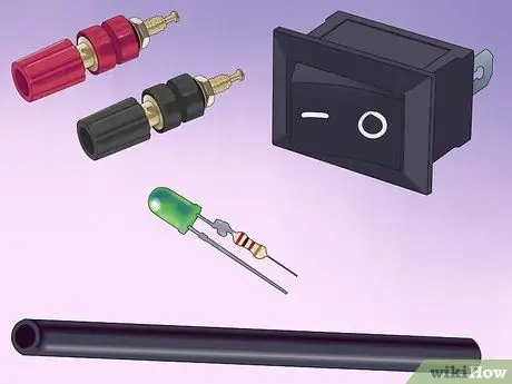
Step 6. Get the parts you need:
speaker connectors (terminals), a led with limiting resistor, a switch (optional), a power resistor (10 Ohm, 10W or more, see the Recommendations section) and heat shrink tubing (alternatively, electrical tape).
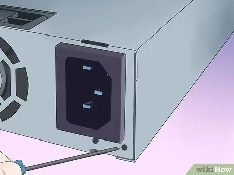
Step 7. Open the power supply unit by removing the screws from the top and bottom of the outer cover
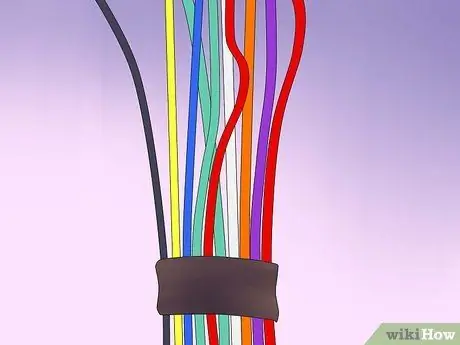
Step 8. Group threads of the same color
If you see wires of different colors than those listed (brown, etc.) consult the Tips section The colors symbolize the voltage value: Red = + 5V, Black = Ground (0V), White = -5V, Yellow = + 12V, Blue = -12V, Orange = +3, 3, Purple = + 5V Standby (not used), Gray = power on (output) and Green = PS_ON # (enable).
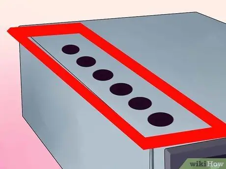
Step 9. Drill a free area of the external cover of the power supply
The holes must allow the fixing of the wires grouped by color. You can also drill holes for the LED and the power switch.
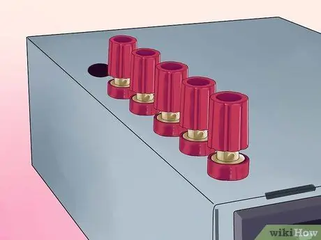
Step 10. Secure the speaker connectors in the corresponding holes and screw behind a bolt
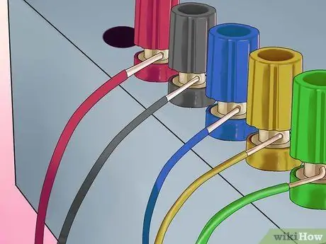
Step 11. Connect the various pieces
- Connect one of the red wires to the power resistor, connect all the other red wires to the red speaker connector.
- Connect one of the black cables to the other end of the power resistor, another black cable to the cathode (smaller connector) of the LED and another to the DC-On switch. All remaining black cables must be connected to the black speaker connector.
- Connect the white cable to the connector for -5V speakers, the yellow one to the connector for + 12V speakers, the gray one to a resistor (330 Ohm) that must be attached to the anode (the longest connector) of the LED.
- Some power supply units may have a gray or brown wire to represent "good power". Many power supply units have a small orange wire used as a 3.3V sensor. This cable is usually mated to the connector by another orange cable. Make sure this cable is connected to the other orange cable, otherwise your laboratory power supply will not turn on. To make the power supply work, the brown (or gray) cable must be connected to an orange cable or a red cable. If in doubt, try the lowest voltage cable (+3.3V) first. If you work on a different power supply unit, you may find different colors. Be sure to refer to the location of the cables attached to the drive connectors, rather than the colors.
- Connect the green cable to the other terminal of the switch.
- Make sure the soldered outlets are insulated in the heat shrink tubing.
- Organize the cables with tape or zip ties.
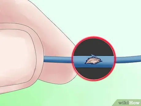
Step 12. Verify that the connections are secure by gently tugging on them
Check for bare wires and insulate them to prevent short circuits. Use a bead of strong glue to glue the LED into its housing. Replace the power supply cover.
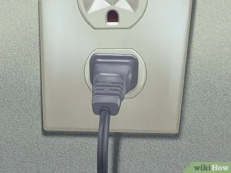
Step 13. Connect the power cord to the unit and plug it into an electrical outlet
Turn on the main switch of the unit, if it is present. Check that the LED lights up. If it does not turn on, start from the switch you placed on the front. Connect a 12V light bulb to the different sockets to check the power supply. To be on the safe side you can use a digital voltmeter. Make sure no cables are shorted. The result should be a beautiful object with a good functioning!
Advice
- You can use the 12V output of the power supply to recharge car batteries. In any case, be careful, if the battery is too low, the power supply short-circuit protection system triggers. In this case, in order not to overload the power supply, it is better to insert a 10 Hom resistor, 10-20 W, in series together with the 12V output. Once the battery has reached the 12V charge (you can use a tester to check this), you can remove the resistor to allow the rest of the battery to charge. This consideration can be useful if you have a car with an old battery, if your car won't turn on in winter, or if your battery has run out after leaving the car lights on all night.
- If you don't feel like soldering 9 cables to the speaker connector (as in the case of grounding cables), you can cut them at the height of the motherboard. You can remove one to three cables. You can also cut all those cables that you are not going to use.
- The voltages that can be output from this power supply unit are as follows: 24V (+12, -12), 17V (+5, -12), 12V (+12, 0), 10V (+5, -5), 7V (+12, +5), 5V (+5, 0). These voltages should suffice for most electrical tests. Many ATX power units with a 24-pin motherboard connector do not have the -5V connector. If you need this voltage, get a power supply unit with 20-pin, 20 + 4-pin connectors, or an AT unit.
- The fan of a power supply unit can be particularly noisy. It is designed to cool the relatively heavy-straining drive and the computer. Of course you can remove it by cutting it off, but that wouldn't be a good idea. A better idea is instead to cut the red cable to the fan (12V) and connect it to the red cable that comes out of the power supply (5V). This will cause the fan to move much slower and therefore be quieter, but still provide a source of cooling. Do not consider this hypothesis if you plan to overload the power supply; evaluate the situation and proceed by trial and error. Alternatively, you can always replace the fan with a quieter one (although you will have to solder it).
- If there is a 3.3V sensor cable, know that connecting the 3.3V part of the power supply using the 3.3V voltage as a voltage converter against 12V (for example) to obtain 8.7V will NOT work. Using the voltmeter it seems that there is actually a voltage of 8.7V, but if you charge the device at 8.7V, the unit can enter protective mode and shut down.
- Some power supplies require the green and gray cables to be connected together.
- Test the power supply unit on a computer before starting, if you're not sure how it works. Test the power on of the computer and the power supply fan. Check if there is enough space for the holes and connectors for speakers. To test this you can plug the voltmeter connectors into an additional socket (for disk drives). It should give a reading of about 5V (between the red and black cables). It may happen that the power supply unit chosen seems dead because the outputs are discharged or because the enable signal (green cable) is not connected to earth.
- You can add a 3.3V output (to power 3V devices, for example) to the power supply by hooking the orange cables to a speaker connector (making sure that the brown cables remain attached to at least one orange cable). Be careful, however, because these cables have the same output voltage with the 5V ones, and therefore it is better not to exceed the total output voltage of these two ways.
- You can take advantage of the hole left by the power supply unit wiring to install a car cigarette lighter socket. This way you can connect car devices to your power supply.
- If the power supply unit does not work, that is, the LED does not turn on, check that the fan is switched on. If the fan is on, then the LED has not been connected well. Probably the positive and negative poles of the led have been reversed. Open the power supply unit and move the purple or gray cable around the LED (be careful not to bypass the LED resistance).
- Options: If you don't need another switch, connect the green and black wire together. The power supply unit will be controlled by the rear switch, if present. If you don't need an LED, ignore the gray wire. Cut it out and isolate it from the rest.
- The + 5VSB line is a + 5V standby line (for the operation of the motherboard buttons, or for the LAN activation function). Normally this line supplies 500 to 1000 mA of current, even when the main sockets are “off”. It may be useful to connect an LED to this line, to have an indicator of power on of the power supply.
- ATXs are switching power supplies (for more information see https://it.wikipedia.org/wiki/Alimentatore#Switching_o_.22commutation.22). To operate correctly they must always have a charge. The resistance serves to "download" the energy, releasing heat. For this reason it must be mounted on the metal wall, which provides a greater source of cooling (you can also mount a heat sink on the resistor, as long as it does not short out with the other components). If you plan to always keep something connected to the power supply, you should not insert the resistance. You can also try using an illuminated 12V switch, to give the charge necessary to turn on the power supply.
- Feel free to decorate the outside of the power supply as you wish.
- You can get more space if you mount the fan on the outside of the cover.
- Maybe you will need to make some holes a little wider.
- Some power supplies have cables that have the function of "voltage sensors" and that must be connected to the cables on which the voltage passes in order to function correctly. In the main wire group (the one with 20 wires) there should be 4 red wires and 3 orange wires. If there is only one or two orange cables, there must be another brown cable connected to the orange. If there are only three red wires, another wire (usually pink) must be connected.
- If you feel like welding, you can replace the 10W resistor with the power supply fan inside. Be careful, however, to match the two polarities.
- The -5V line has been removed from the ATX specification and does not exist on all ATX power supplies.
- If you intend to use the power supply for objects with a high initial charge, such as a 12V fridge with a capacitor, connect a suitable 12V battery to avoid tripping the unit.
Warnings
- Do not touch any lines connected to the capacitors. Capacitors are cylinders, wrapped in a thin layer of plastic, with the top metal exposed and usually marked with a + or a K. Tantalum capacitors are smaller, slightly larger in diameter, and have no plastic cover. These capacitors retain energy more or less like a battery would, but unlike them they can discharge much faster. Even if you have unloaded the unit, avoid touching parts of the power supply you don't have to work on. Before starting any work, use a probe to dump everything you could touch to the ground.
- If you think the unit is damaged, don't use it! If it is damaged, the protection circuit may not work. Normally the protection circuit discharges the high voltage capacitors slowly; but if, for example, the unit was connected to 240V while it was set to 120V, the circuit could be skipped. If this circuit does not work, the unit may not shut down in the event of an overload or failure.
- The mains voltage can kill (any voltage above 30mA / V can kill you in a heartbeat if it can penetrate your skin) and, in minor cases, cause a severe shock. Make sure you have removed the power cable before making the conversion and have discharged the capacitors, as described in the previous steps. If in doubt, use a voltammeter.
- Make sure you have discharged the capacitors. Connect the power supply to the socket, turn it on, short the Power cable (the green one) to ground, then disconnect the power supply when the fan stops spinning.
- When you pierce the external cover, make sure that the filings do not come into contact with the internal circuits of the unit, as it could cause short circuits and consequently develop flames, excessive heat or dangerous sparks.
- A computer power supply is a good alternative if you just want to do tests, or to turn on small electronic components (eg battery chargers, soldering irons) but it will never produce energy like a real laboratory power supply. If you intend to use the power supply for more than a few small tests, buy a good laboratory power supply. This is why they cost so much.
- The power supply you have created will provide a good current output. If you make a mistake you could create electric arcs on the low voltage outputs or you could fry the circuits you are working on. It is for this reason that laboratory power supplies have an adjustable current limiter.
- This operation should only be performed by those who are experts in power supplies.
- This type of operation undoubtedly cancels the warranty of the power supply.
- Make sure you ARE NOT grounded when working on the power supplies, so as not to allow electricity to pass through your body.


